
Drilling for water
Host: Hodgson River Station
Written by Jo Bloomfield – Owner, Hodgson River Station.
I’m trying to focus on ‘change’ this week and have twisted the arm of my father in law (Pop) who has an incredible memory for detail, he used to drill for water in his younger days.
Well digging.
Is in its very basic form well sinking is literally digging a hole to access water below the ground’s surface then bucketing the water out to get it to the surface for use by animals or people.
An area was marked out, usually 6’ x 4’ and squared to form the basic open hole that would be the well and dug straight down. At the beginning of excavation, a hole was dug until the sides begun to cave or fall in. Once this started a set of timbers were framed to suit the hole that was called the ‘horn’, it sat over the hole and slid down the walls as the soil was excavated underneath by the digger inside. More timbers would be added at the top as the ‘horn’ moved down. If hard rock or the horn frame stopped moving then it was ‘set’ onto ledge of rock and the walls frame boards were added to under the ‘horn’ set as the earth was removed. Braces and cross beams were kept in place to hold the wall planks or logs against the well sides and until the final setting of the walls was carried out. This enabled the digger to maintain squareness and integrity of the walls so they wouldn’t collapse in. If a particularly soft soil area was found, such as sand then a smaller excavation was made and another horn set used to suit that hole size.
Built over the top of the hole was a four post frame that looked like a skeleton shed with legs and roof rails. It would be built in the early stages of beginning to dig to assist in removing soil. It would support a pulley and allow ropes or cable to lower and lift buckets that operated to dump the soil at the surface on the outside of the hole. Another form of lifting was called a ‘Chinaman’s whip’, it was a lever pivoted at the side of the well on which the end was centred over the well opening with a cable and bucket. As the lever was worked up and down the bucket would drop into the well, retrieve soil or water and then weighted and levered to rise to the surface, this was normally by manual labour. The bucket was then tipped over the side of the wall to empty soil or water into a trough. This method was only suitable for water levels close to the surface or else the pulley system was used to deeper levels. Occasionally a horse, donkey or mule would be used to operate a pulley system.
Wells relied on shallow water aquifers being available; therefore they were often located in river beds. Local timbers were used to line the walls. Manual physical labour by hand, dug and hauled the sediment out of the hole once the soil was loosened. If a particularly hard area was encountered, often dynamite was used to dislodge rocks and allow deeper digging. Wells were slow and laborious to build but once a supply of water was found could enable large discharge if the aquifer rose in the well as the source fed from the base. If a supply wasn’t sufficient the well would be deepened.
If the water level was keeping up with the digging or required bailing each day before digging started then the general rule was that it was a good supply of water and digging stopped.
When the required depth was obtained a final ‘Collar’ was made that sat on the surface. It was a set of timbers that stuck out above the surrounding ground and stopped soil and fill in around the well by rain or sediment.
Well buckets were generally a very heavy steel about 2’ tall and 1’ round. If the soil was dry the buckets would simply be up ended at the surface. If they were working with slurry or bailing water, a trap door in the base of the well bucket would close as the weight of its contents filled, usually a small steel opening of 6” square lined with tyre tubing or rubber as a seal. When pulled to the surface the trap door would be pulled open via chain inside the bucket or spike poke up from the outside. This allowed the contents to flow out from the base and the bucket would remain upright, when emptied it was sent down the well again to be refilled.
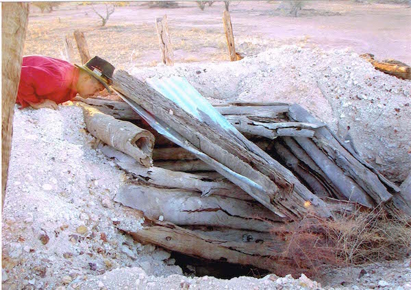 Source Jo Bloomfield. Mt Dare station South Australia. 2004. An old collapsed well.
While digging was extremely labour intensive it was a job often carried out in the hotter months, due to other station requirements of mustering in the cooler ones. Working down the wells was pleasant temperature wise as it was cooler than the topside temperatures.
The mud puncher or percussion rig
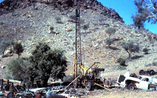 Mud puncher with its derek up.
This was Pop’s drilling rig; he brought and used this while waiting for my husband to be born. It is pictured with its derek (mast) up which requires stabilisation by anchored cables to control movement while working. The diesel engine is at the end near the tow hitch end.
The engine drove wheels which could be ‘thrown in or out’ to grip belts or cogs that worked the large drum on which the cable was wound. Depending on hand levers the cable drum would spin clockwise or anti clockwise thus controlling up or down of the cable.
 Source Bird. Mud puncher engine set up.
The 9/10 strand high tensile steel cable was fed from the drum through pulleys and wheels up over the top of the derek and then used to suspend the tools that will make a bore hole in front of the derek. The cable was tied to special attachments that allowed quick coupling and changing of tools.
Tying of a ‘thimble’ and a swivel head allowed the tools to be attached by tapered thread. The threads you see on normal bolts and things are parallel, to grip the item these have to be wound all the way to make a tight grip. Tapered only takes a couple of turns and all threads grip. But as quick and strong as it was it also could came un- done just as quick and to have a thread come undone while gear is down a hole was disastrous. So careful attention was always paid to ‘doing up threads’. A driller has to be meticulous regarding the cleaning and oiling of threads to make sure they are clean and dirt free. Tapered threads lock into place and require large tools and usually two men at a time to tighten and loosen them when changing the gear.
Everything is heavy with rigs, in that nothing has changed! It was all manual labour with sometimes other pulley’s able to assist as lifting tools. The only thing light around these machines “was the tin of tobacco in your pocket”. Some of the tools 6’ long handles and were heavy and awkward to use. “Man Killers”.
The actual digging tools that were used to dig the hole were the cutting tool, or sinker bar, it was like an oversized blunt chisel bit 10” across, with a two edged cutting surface, others were a star shape in that they had 4 cutting surfaces. About 10’ long and solid steel, the heavier it was the better it hit. Pop used the larger 10” as they allowed easier inserting of casing (8”) and latter pumping equipment (usually 3-4”).
By working the cable on the pulley the ‘sinker’ would be dropped and lifted repetitively. The turn it created in its momentum was due to the spring cable twist of the left hand lay of the cable, which would continue to turn due to the swivel at the top of the tool, when taut and then released the natural movement of the cable was to spring the tool in a turning action after a hit. It was a practiced skill to know how ‘weighted’ your cable was.
The ‘mud puncher’ sinker only loosened the soil, the soil or rock fragments still had to be removed from the hole. Water was put down the hole in measured amounts to make sure slurry was created and then the ‘sinker’ would be bought to the surface and replaced with a ‘bailer’.
Using the clacker valve technique of the well buckets, the ‘bailer’ was a long hollow pipe with the clacker in the base. As the pipe was dropped into the slurry the clacker would be forced open letting the slurry go into the inside of the pipe and then close as the weight of the contents then came back onto it when lifted. Again the ‘weighting’ of the cable would tell the operator if the bailer was full or not. If it was full then it was lifted back out. As the bailer was lifted free of the hole it was put over the spike of a drum located close by to open the clacker, releasing the contents and thus start the whole process again. It could lift 2-4 gallons at a time. Often a stone or something would lodge the clacker and therefore many dry runs would happen of empty bails. As the loose contents of the hole were removed after about each 1m gained the ‘sinker’ was re-connected and the whole process started again.
Pop’s ‘Mud puncher’ machine had about 300’ cable which gave an effective drill depth to about 250-280’. The speed of drilling depended on ground type, sometimes softer sandstones enabled many feet to be dug a day, in rock maybe only one to two feet a day. It was slow work but gave a good clean hole of 10” to depths that most wells could never reach. The hole he dug when my husband was born was 35’ and took him 4-5 days, he obtained 350 gallons an hour. Ginty Gorey (Later Gorey Bore drillers – Alice Springs) would latter dig another bore in the same area using a rotary rig at the same place and it took them 2-3 hours to drill 100’, they only obtained the same water supply.
Casing was done after drilling to maintain the bore hole shape. Casing is very heavy walled pipe with a thread one end and a belled slot at the other. All screwed together, these days most casing is welded. Slots were cut in the casing to allow water flow into the bore at the base
Rotary/air operated rigs.
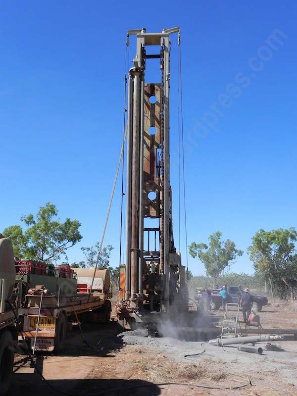 Rotary rig – Modern day drilling rig that uses compressed air and hydraulic pressure to drill.
These rigs operate with a large diesel engine and hydraulics to push and pull the drill head up and down the mast as well as rotate the head drive that connects to the rods. A large air compression system operates to force the hammer head to work that is drilling the hole and the pipes used to connect the head to the drill bit are very, very heavy hollow pipes.
Using hydraulic pressure and highly compressed air these rigs drill and clean the bore hole at the same time.
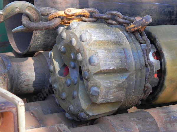 Drill bits of the rotary rigs, air forces the hammer head to bang very fast, the teeth are quiet worn on this one.